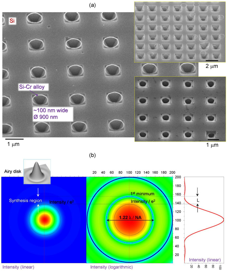
Figure 4.
(a) SEM image of Si-Cr alloy ring formed at the rim of ablated pit in the Cr mask; imaged after KOH etch of Si (inverted pyramids are formed) and Cr-etch removal of the laser unexposed regions of Cr. Insets shows conditions of KOH over-etch when opening of the pyramidal pit becomes larger as diameter of the ring. (b) Intensity distribution of a plane wave at the focus in linear and logarithmic scale; the inset shows a 3D envelope of the intensity profile (grey).

