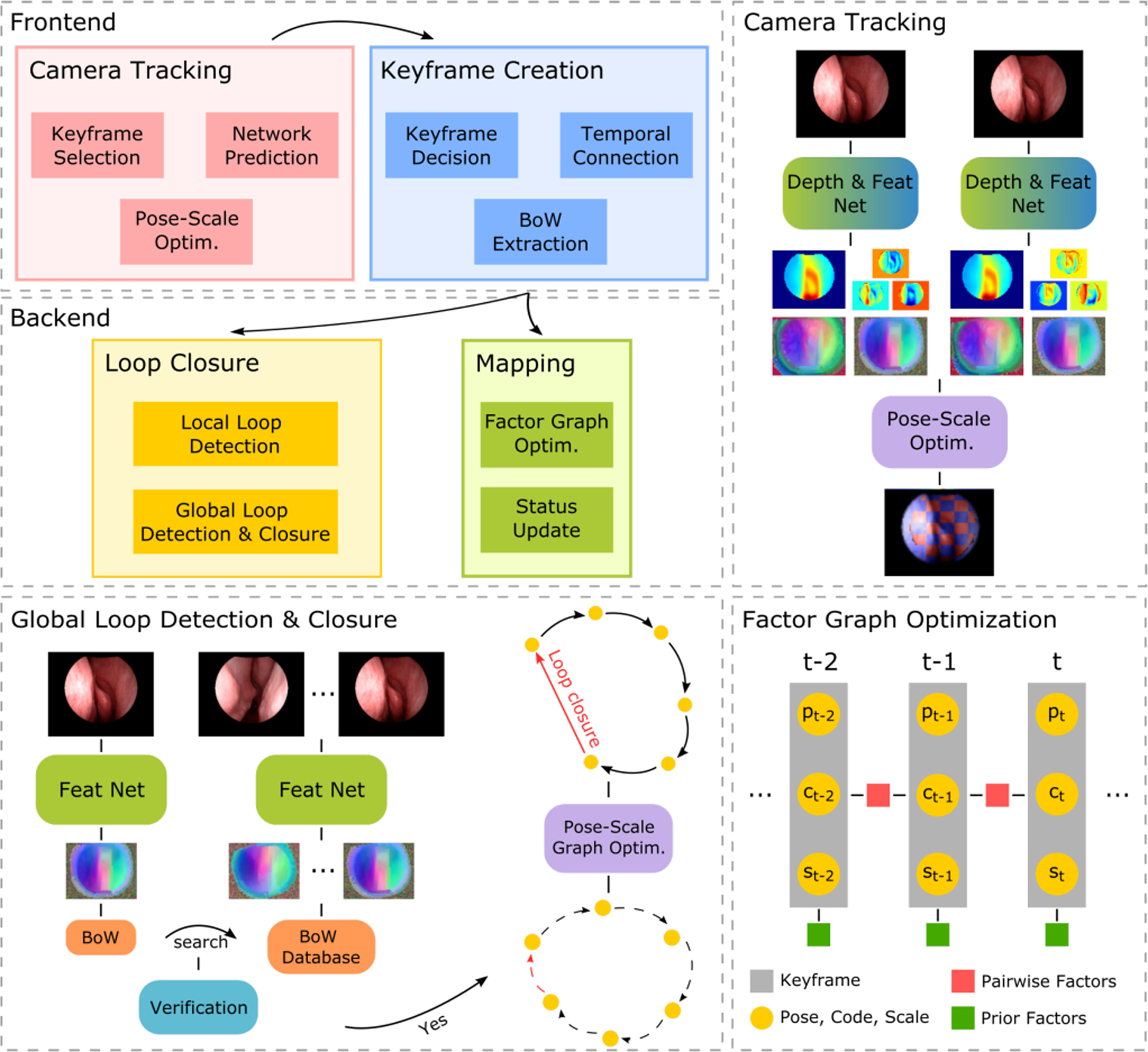
Fig. 1: Overall diagram of SLAM system.

The top left shows the module relationship in our SLAM system. The top right demonstrates the network prediction and pose-scale optimization within the Camera Tracking module. The bottom left shows the process of global loop detection and closure within the Loop Closure module. The bottom right demonstrates the optimization in the Mapping module, where pair-wise factors between non-adjacent keyframes are not shown. More details are described in Sec. IV.
