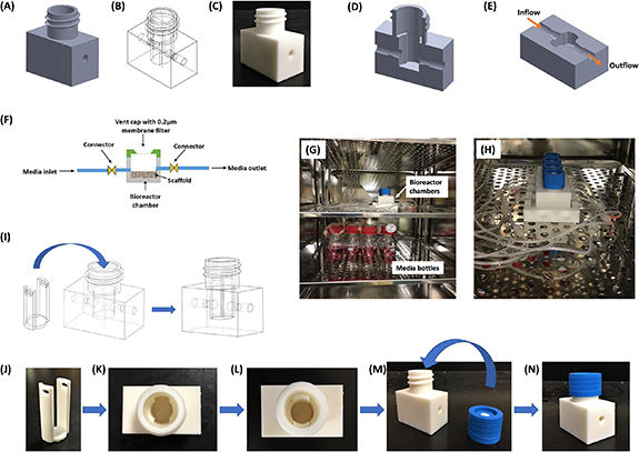
Figure 1.

Bioreactor design (A) CAD design of bioreactor chamber (full view) (B) symmetric view of the chamber (C) 3D printed bioreactor chamber (D) section of side view (E) section of top view. Arrow indicates inflow and outflow fluid directions (F) schematic representation of bioreactor and their components with flow directions. (G), (H) Bioreactor assembly setup inside the incubator (37 °C, 5% CO2, and high moisture content) (G) bioreactor chambers (top rack) connected to media bottles (bottom rack) via tubing (H) enlarged view of bioreactor chambers positioned inside the incubator. (I) Symmetric view of the chamber and holder showing steps of holder insertion into bioreactor chamber (J)–(N) assembly of bioreactor chamber (J) scaffold holder (K) top view of bioreactor chamber (L) top view of the bioreactor chamber inserted with scaffold holder (M) bioreactor chamber and vent cap (N) vent cap fitted bioreactor chamber.
