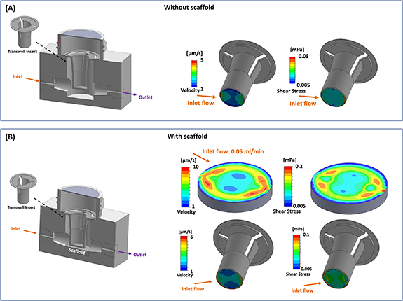
Figure 5.

(A) Bioreactor assembly with transwell insert without scaffold (upper left), velocity and shear stress distribution on transwell membrane surface at inlet flow of 0.05 ml min−1 (upper right). (B) Bioreactor assembly with transwell insert and scaffold (lower left), velocity and shear stress distribution on the scaffold and transwell membrane surface at inlet flow of 0.05 ml min−1 (lower right). Arrows represent the direction of fluid flow.
