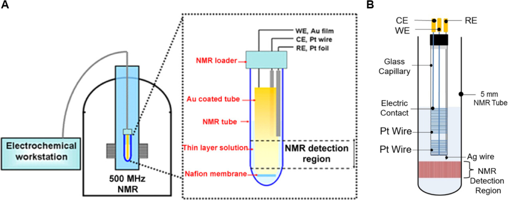
Figure 13.

(A) Schematic representation of an in situ EC-NMR spectroscopy setup with the working electrode being in the NMR detection region (inset illustrates NMR tube with working electrode (WE), counter electrode (CE) and reference electrode (RE), along with a Nafion™ membrane providing a divided cell. (B) Schematic representation of an in situ EC-NMR spectroscopy setup with the working electrode being outside of the NMR detection region (inset illustrates NMR tube with working electrode (WE), counter electrode (CE) and reference electrode (RE). [Figure A reproduced from ref 339. Copyright 2017 American Chemical Society. Figure B reproduced from ref 340 Copyright 2019 Elsevier B.V.]
