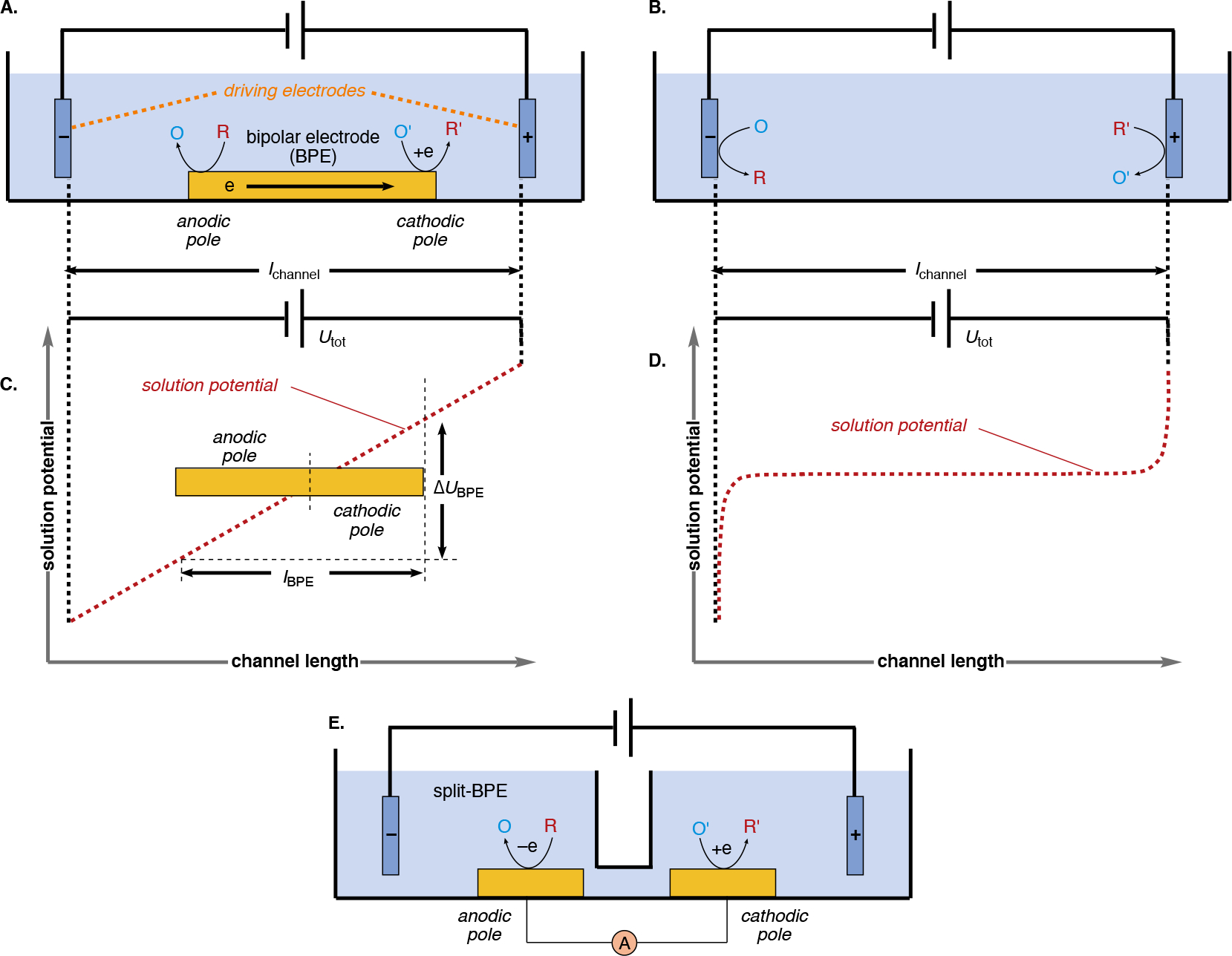
Scheme 117.

A comparison of the experimental set-ups for open bipolar electrolysis (A) and conventional electrolysis (B). An approximately linear gradient electric field is present in the bulk of the solution between bipolar electrodes due to the low concentration of supporting electrolyte (C), while in conventional electrolysis electric fields are localized at the electrode surface (~exponential decay over tens of Angstroms) as a high concentration of supporting electrolyte is used (D). (E) An example of a closed, split bipolar electrode setup. Note: O, O', R, and R' represent oxidized and reduced species occurring at either the anodic pole of the BPE (facing the cathode driving electrode), or the cathodic pole of the BPE (facing the anode driving electrode).
