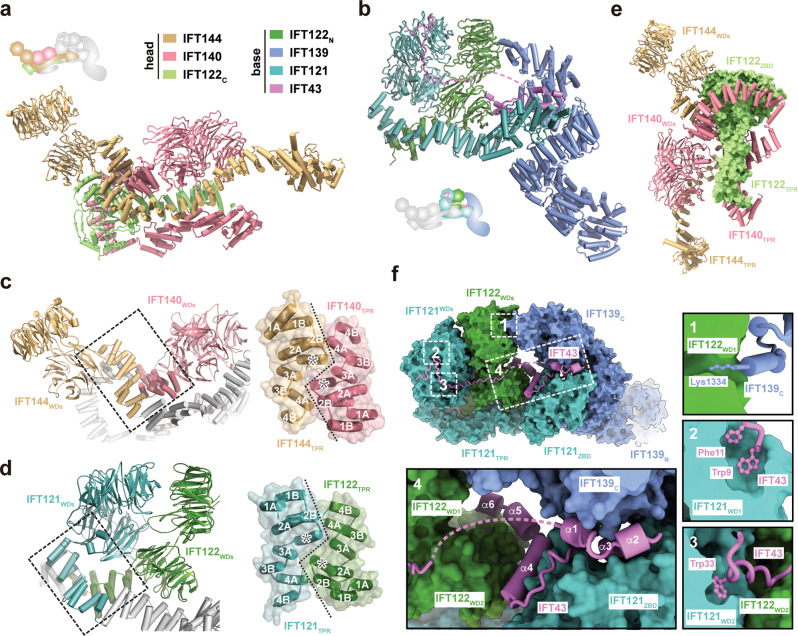
Fig. 2. The head and base modules of IFT-A.
Atomic structures of the head (a) and base (b) modules. The color scheme is shown. The cartoon indicates the relative position of the modules in the elongated state of IFT-A. The pseudo-two-fold symmetric IFT144-IFT140 (c) and IFT122-IFT121 heterodimers (d). The central TPR junctions formed by the first four TPRs are highlighted in black dashed boxes, which are enlarged on the right. The TPRs are numbered and the inserted α-helix in each subunit is labeled with an asterisk. e A different view of the head module with IFT122 shown in the surface representation. f Close-up views of the interaction network in the base module between IFT122WD1 and IFT139C (1), between IFT121WD1 and IFT43 (2), between IFT121WD2 and IFT43 (3) and between IFT43 and IFT139-IFT121-IFT122 (4).

