
Fig. 3.
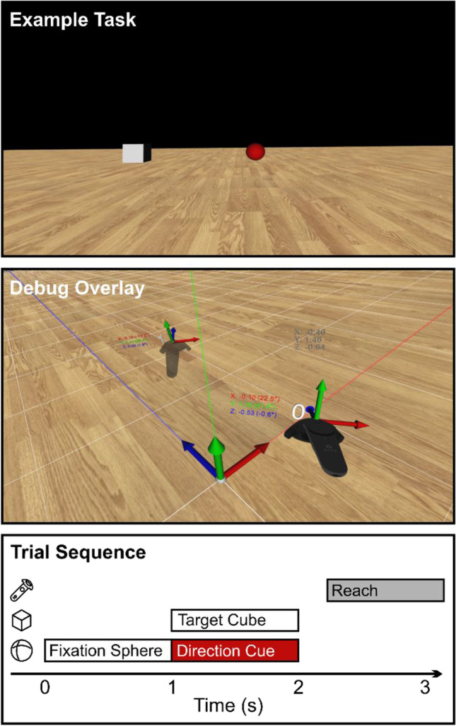
Screen captures of our example VR environment and illustration of the trial sequence. Top: Screenshot from the case study pro-/anti-reach task described in Sect. 3. The displayed stimulus arrangement instructs the participant to reach opposite (red fixation sphere = anti-reach) of the presented target position (gray cube). Middle: Example scene with the SteamVR debug overlay enabled. Coordinate axes, alignment lines, and white grid visualize Vizard’s world coordinate system. Dark gray numbers indicate HMD position (shown as heads-up display to the user). Two Vive controllers are shown with their index in Vizard’s controller list, current position and Euler angle data, and axes denoting their local coordinate system. Bottom: Trial sequence in the example paradigm, corresponding to the scene shown in the top panel. A white fixation sphere (sphere icon) is shown for 1 s, then changes color to red to indicate an anti-reach. Simultaneously with the color change, a target cube (cube icon) is displayed for 1 s. After both cube and sphere disappear, the participant performs a reach movement with the controller (gray; controller icon). Icons by Ben Davis from NounProject.com