
FIG. 1.
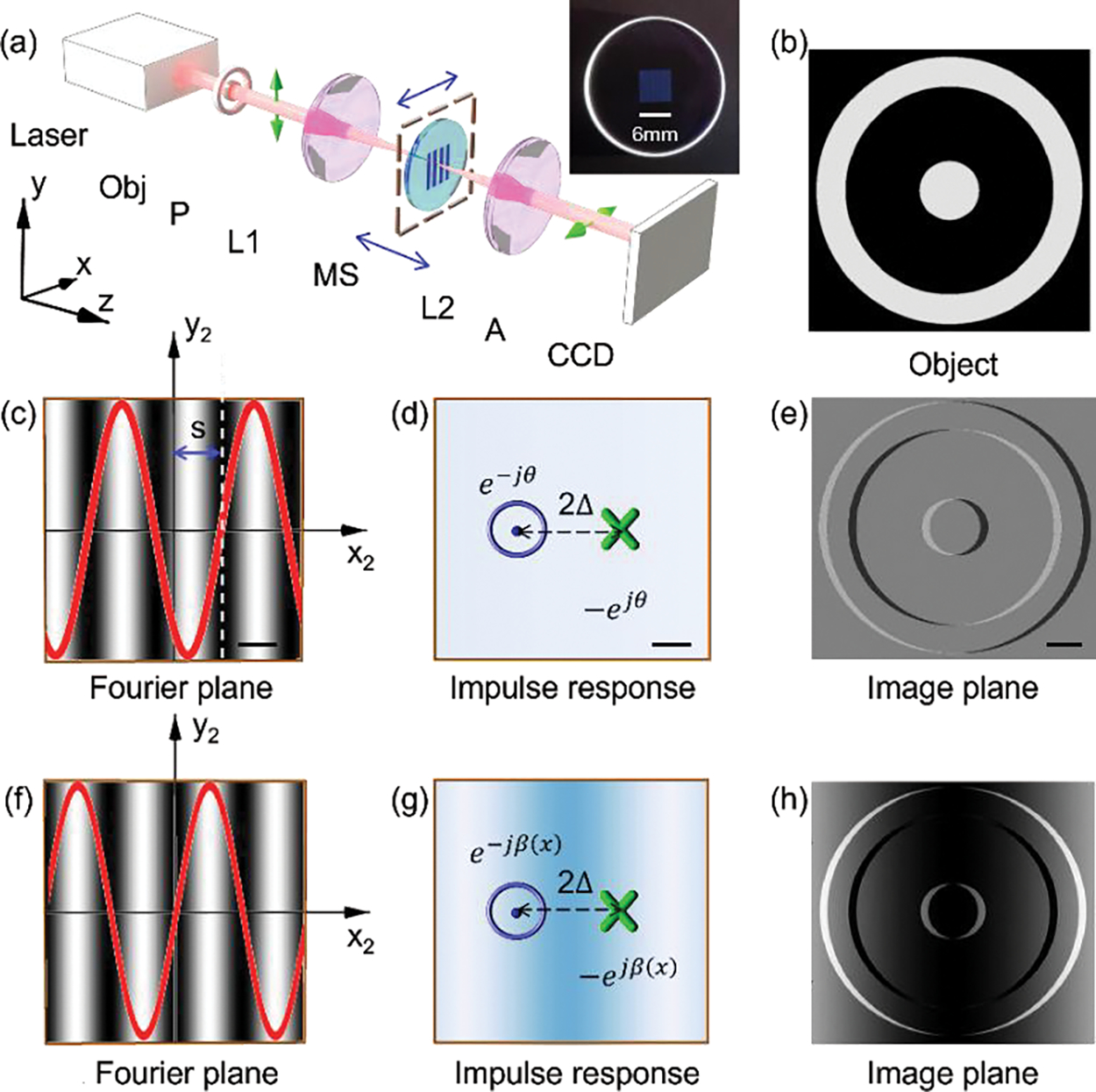
Concept of the proposed FOSSM. (a) Experiment setup. Obj, Object. P, Polarizer. L, lens. MS, metasurface. A, analyzer. Blue arrows indicate the translation direction of the metasurface. Inset, photograph of the MS. The setup is a typical 4f system composed of two lenses L1 and L2. To realize the proposed function, a MS is inserted near the Fourier plane of the 4f system, along with a pair of crossed polarizers (P and A). (b) The used phase object with unity amplitude. The photograph of the metasurface, patterned area, 6 mm*6 mm. (c-e) The concept of retardance imaging of the object with a laterally (along x direction) displaced metasurface. Scale bar in (c)-(e): 150 μm, 0.8 μm, 10 μm. (f-h) The concept of retardance imaging of the object with a longitudinally (along z direction) displaced metasurface. The fringes in (c) and (f) show the effective transmission. The red curve in (c) and (f) is the cross section of the amplitude transmittance profile of the metasurface along x direction.