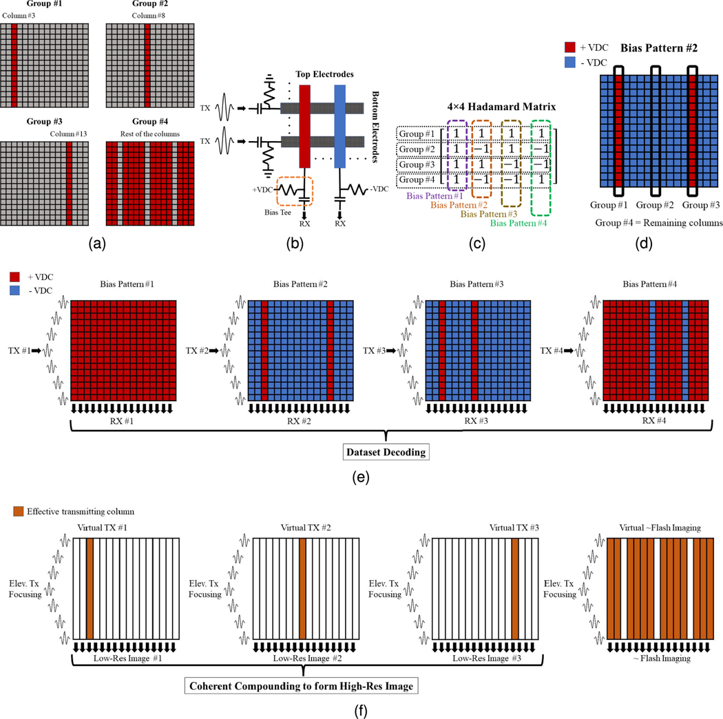
Fig. 2.
uFORCES imaging scheme illustrated with a 16 × 16 TOBE array using four transmits (four bias patterns), (a) Column groupings for arbitrarily selected sparse transmitters, (b) Schematic of the top and bottom electrodes and their bias tees, and (c) 4 × 4 Hadamard matrix for this example. One column of the Hadamard matrix is used as a biasing pattern for each transmit event, (d) Applied coded bias voltage pattern associated with bias pattern 2, (e) Illustration of the uFORCES imaging scheme for all the bias pattern sequences with transmitting on the rows and receiving on the columns, and (f) sparse synthetic aperture effective dataset and reconstruction scheme after aperture decoding with an inverse Hadamard matrix.

