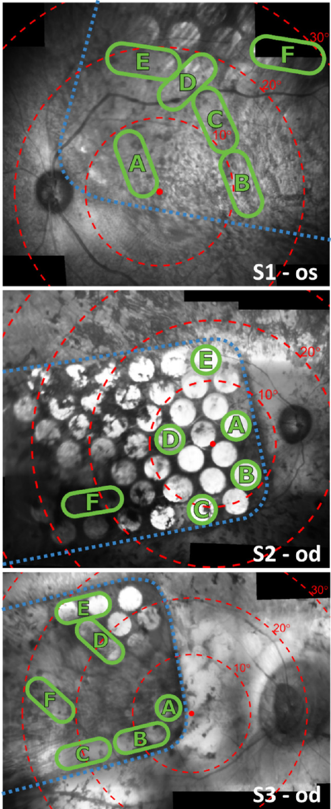
Figure 1.

Near-infrared fundus images showing the 44-channel suprachoroidal retinal implant within the eye for each subject. The dashed blue line indicates the edge of the implant. Electrodes are visible as bright circles (some are hidden behind pigmentation). Concentric red circles indicate 10° eccentricities of visual field centered on the fovea according to the Drasdo and Fowler schematic eye.37,38 Green circles denote the subset of electrodes that were selected for stimulation in the phosphene mapping tasks. Green ovals encompassing two neighboring electrodes indicate they were operated as a shorted pair to adhere to per-electrode charge density limits.
