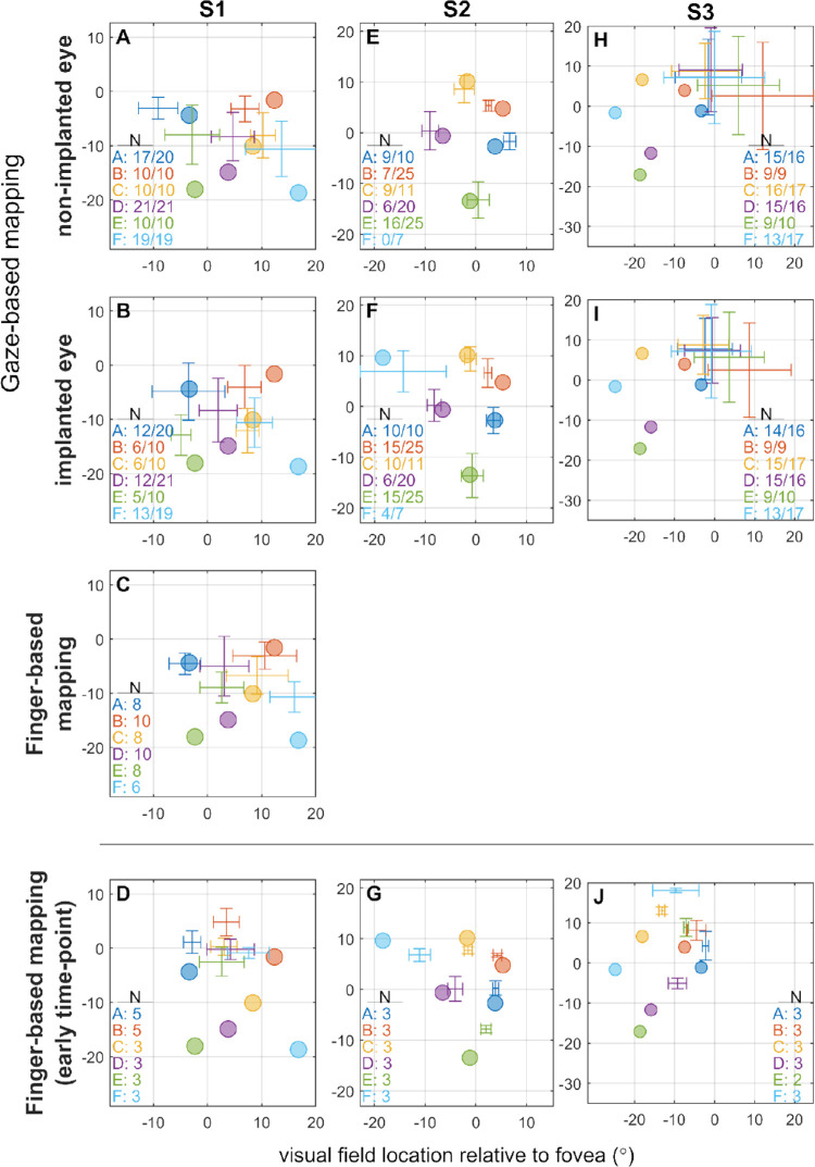
Figure 3.
Comparison of retinotopic electrode locations to the estimated phosphene locations in the finger-based and gaze-based phosphene mapping tasks. Colored circles indicate expected phosphene locations, determined by the retinotopic placement of the electrode according to the Drasdo and Fowler schematic eye.37,38 Crosses with error bars indicate estimated perceived phosphene location relative to the fovea as measured by the behavioral response (mean ± SD). Text in the lower corner of each panel indicates the number of trials included in the dataset per phosphene, and for gaze-based mapping the number after the stroke indicates the total number of trials performed including those discarded owing to artefact in the eye tracker signal. For any given trial of the gaze-based mapping task, data from one or both eyes were discarded if it contained excessive artefact, resulting in uneven numbers of trials between the nonimplanted (A, E, and H) and implanted eyes (B, F, and I) in some cases. Note that no data is available for S2 nonimplanted eye for phosphene F (light blue), because the pupil of the nonimplanted eye fell out of eye-tracker range during large leftwards movements. (C) S1 performed a touchscreen finger-based mapping task at the same time-point as gaze-based mapping. (D, G, and J) Participants also performed a finger-based mapping task at an earlier time-point.

