
Figure 2.
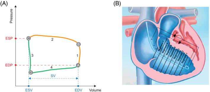
Schematic representations of (A) a pressure–volume loop of the right ventricle and (B) the conductance catheter positioned in the right ventricle. In the pressure–volume loop schematic, a indicates the closure of the tricuspid valve and end of diastole (shown in green), b indicates the opening of the pulmonary valve and end of the isovolumetric contraction (1), c indicates the closure of the pulmonary valve and end of the ejection phase (2) and systole (shown in orange), and d indicates the opening of the tricuspid valve, end of isovolumetric relaxation (3), and beginning of the filling phase (4). EDP, end‐diastolic pressure; EDV, end‐diastolic volume; ESP, end‐systolic pressure; ESV, end‐systolic volume; SV, stroke volume.