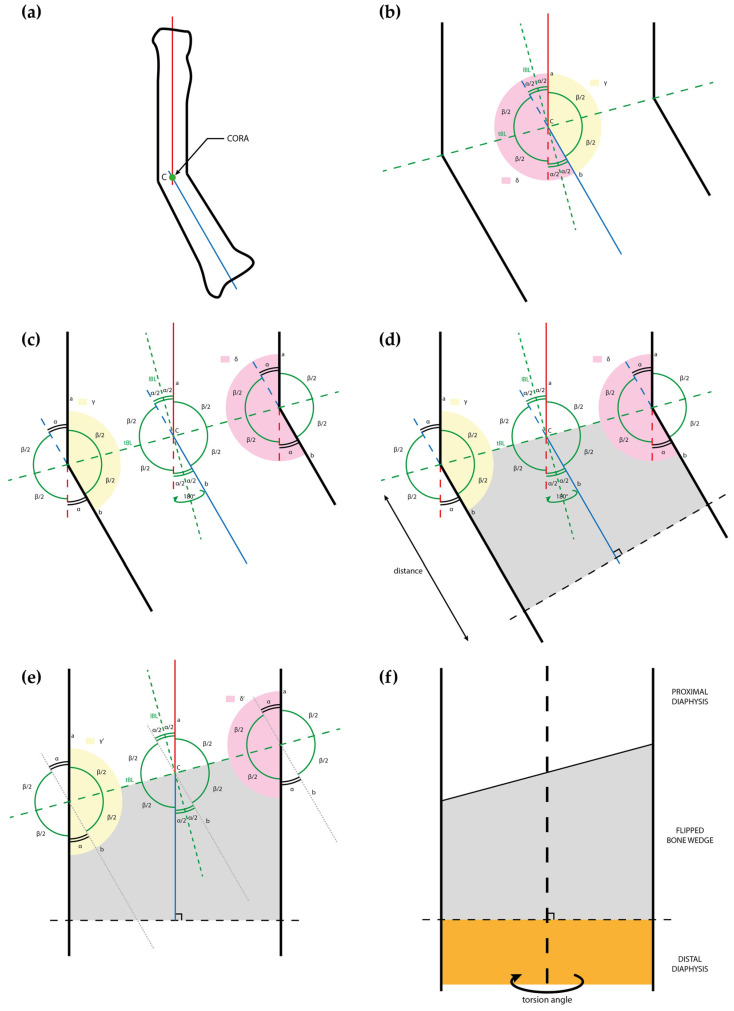
Figure 3.
Drawings representing the steps of the flipping-wedge osteotomy and its geometrical demonstration: (a) drawing of a deformed radius sectioned along the plane of maximal deformity with the proximal and distal axes (respectively red and blue), which meet at the center of rotation of angulation (CORA); (b) at the CORA, the angular deformity (α) and its supplementary angle (β) are identified, and the respective longitudinal bisector line (lBL) and transverse bisector line (tBL) are drawn as dotted lines. A concavity angle (γ) and a convexity angle (δ) are colored in yellow and pink, respectively; (c) γ and δ overlap with the concave and convex shapes of the bone; (d) in this example, a bone wedge is identified (gray) between the tBL and a line perpendicular to b (black dotted line) at any desired distance from the CORA; (e) the gray wedge is flipped 180° and, according to the Proof of Theorem 1, the new concavity (γ’) and convexity (δ’) angles are both equal to 180°; and (f) rotational alignment can be further adjusted on the perpendicular plane, in this example by freely rotating the orange segment distal to the perpendicular cut. CORA = center of rotation of angulation; lBL = longitudinal bisector line; tBL = transverse bisector line.

