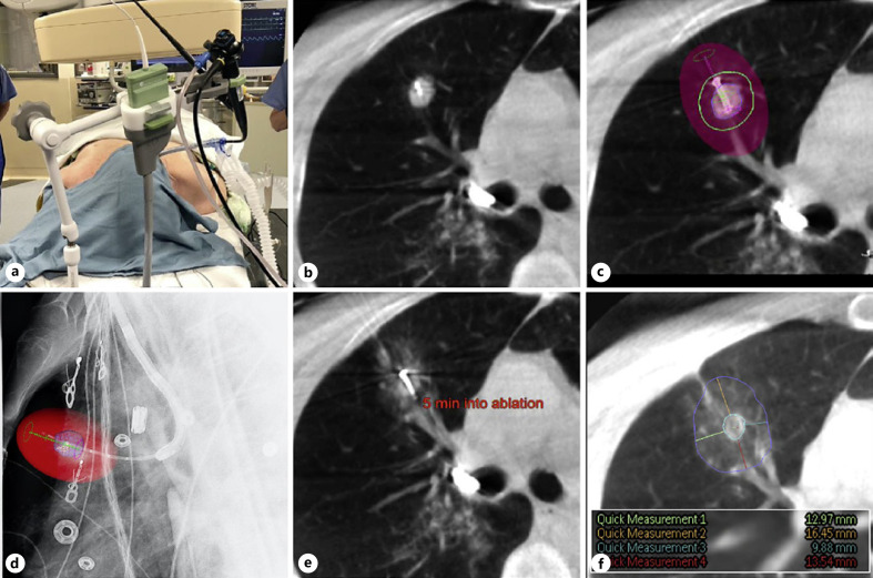
Fig. 1.
Patient positioning and images of the ablation procedure as obtained by CBCT with AF and Philips Lung Suite software for real-time measurements. An operating room photograph (a) and 5 consecutive CBCT or AF images from 1 representative patient who was treated for a 14 × 13 mm tumor in the upper lobe of the right lung are shown. a NeuWave bronchoscope holder with integrated attachment for the MWA catheter. This was used during all CBCT scans and for the ablation itself. b Axial CBCT image showing the probe positioned within the tumor. c Axial CBCT image illustrating ablation planning: colored spheres indicate the target tumor (blue), the minimal desired margin (green), and the final estimated ablation zone (red shaded area). d Lateral augmented fluoroscopic image confirming the position of the probe: the colored spheres indicate the target tumor (blue) and the final estimated ablation zone (red shaded area). e Axial CBCT image, taken 5 min into a 10-min ablation showing early ground glass changes consistent with ablated lung tissue. f Axial CBCT image, taken 10 min after completion of the ablation, showing the final ablation zone (blue circle) and margin measurements which confirm that adequate margins were achieved (colored lines, inset shows enlarged snapshot of measurements of the margin in mm).

