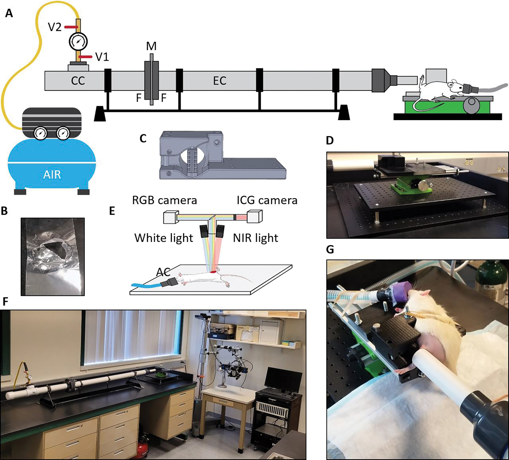
Figure 1.

High-energy trauma model. (A) Schematic of the blast overpressure tube system with the Mylar sheet and animal holder in place. V1 – relief valve, V2 – air valve, CC – compression chamber, M – Mylar membrane, F – flanges bolted together, EC – expansion chamber; (B) Ruptured 3mil Mylar sheet after blast; (C) 3D model of the animal holder; (D) Adjustable platform with installed animal holder; (E) Schematic of the imaging system, NIR – near infrared, AC – anesthesia cone; (F) Compact setup of blast overpressure tube and imaging system in the lab; (G) Anesthetized rat in the holder before a blast with the leg positioned freely close to the output end of the expansion chamber.
