
Figure 6.
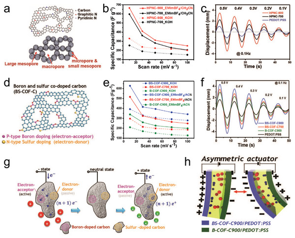
a) Schematic diagram of hierarchically porous nitrogen‐doped carbon (HPNC). b) Specific capacitance values of HPNC‐700 and HPNC‐900 at various scan rates. c) Bending performances of the electrodes under various peak voltages (0.1–0.5 V) at 0.1 Hz. d) Schematic diagram of boron and sulfur co‐doped carbon (BS‐COF‐C). e) The variation in specific capacitances with scan rates in both electrolytes. f) Bending responses of the actuators under varying sine waves. g) Effect of electron mobility and ionic interactions under electric field for BS‐COF‐C with functionally antagonistic co‐doping. h) Schematic illustrations of the asymmetric actuation mechanism of the asymmetric ionic actuator. d–h) Reproduced with permission.[ 94 ] Copyright 2019, John Wiley and Sons.