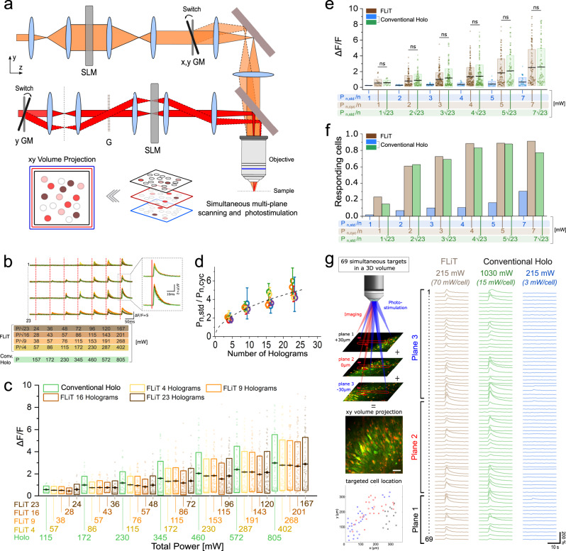
Fig. 4. Multicell all-optical cyclic-FLiT.
a Scheme of the optical setup including: a multiplane imaging system (orange path) and a cyclic-FLiT photoactivation system (red path). Multiplane imaging relies on a SLM-based modulation of the incoming laser which splits the laser in multifoci beams simultaneously scanning axially-shifted planes (red, blue, and black planes). Multiple cells can be independently photoactivated in multiple-planes (red, light-red, and dark-red circles, limited to three planes for representation purposes). GM: Galvo-mirrors, G: diffraction grating. b Representative calcium traces from 4 neurons of a group of 23 co-expressing GCaMP7s and ST-ChroME cells simultaneously photoactivated by varying the illumination mode (cyclic-illumination with H = 4 (yellow line), H = 9 (orange line), H = 16 (light brown line), H = 23 (dark brown line) holograms or conventional steady holography (H = 1, green dashed line) and the illumination powers. Vertical red lines indicate the onset time of each photostimulation episode. The power corresponding to each photostimulation episode is indicated at the bottom with rows of different colors, each indicating the power used in the different illumination modes. Power was adapted such that the total power of cyclic-FLiT was reduced by a factor equal to compared to conventional holographic illumination. The inset represents a zoom of a part of the calcium traces. For conventional holography: total illumination time, for = 23 cells, = 10 ms; For cyclic-FLiT: total illumination time, for = cells, . c dF/F upon multicell all-optical photoactivation based on the illumination protocol depicted in (b). Different colors indicate different illumination modes as indicated in (b). Illumination powers corresponding to different illumination modes are indicated along the x bottom axis. Box bounds and box center indicate standard deviation and mean of the dF/F of all cells photoactivated in each illumination mode, respectively (4 FOV, 365 × 365 µm2, 23 cells simultaneously photoactivated per FOV). Circles indicate the dF/F of each cell. d Ratio of the total illumination power needed in conventional steady illumination and cyclic-FLiT () to induce the same range of dF/F in the photoactivated cells for different numbers of holograms. Circles and bars indicate the mean and the standard deviation of the responding photoactivated cells binned on different ranges of dF/F (0.3<dF/F<0.5 blue, 0.5<dF/F<1 green, 1<dF/F<2 red, 2<dF/F<3 orange, 3<dF/F<5 purple, dF/F>5 yellow). Black dashed line indicates the theoretical factor. n = 23 cells per FOV; 4 FOVs. e, f dF/F (e) and fraction of responding cells (f) upon multicell all-optical photoactivation under cyclic-FLiT with H = 23 holograms (dark brown) and steady conventional illumination (blue) by keeping the same power per cell or by increasing the power of conventional illumination by (green). Box bounds and box center indicate standard deviation and mean of dF/F of all cells photoactivated in each illumination mode, respectively (Kruskal–Wallis test followed by Dunn’s multiple comparison; ns: P > 0.05; 4 2D-FOV, 350 × 350 µm2, 92 cells; 3 3D-FOV, 350 × 350 × 60 µm3, 115 cells). Circles indicate dF/F of each cell. g Left: Schematics of multifoci 2P scanning image of a set of 69 cells simultaneously photoactivated and recorded in a 3D volume. Cells are in three distinct planes 30 µm axially apart. Cells belonging to different planes are simultaneously monitored in a 2D XY volume projected image. Red and green corresponds to ST-ChroME and GCaMP7s labeling, respectively. The locations of the 69 photoactivated cells distributed across the three planes is indicated with different colors in the 2D map at the bottom (black, red and blue circles correspond to cells located in z = 30, 0, −30 µm plane, respectively). Scale bar: 50 µm. Right: Calcium transients associated to the 69 cells located in a 3D volume as depicted on the left, simultaneously photoactivated and recorded under cyclic-illumination with H = 23 holograms or conventional steady illumination (215 mW total power under cyclic-FLiT (brown line) and conventional illumination (blue lines) or mW total power under conventional illumination (green lines)). The corresponding powers sent to each cells are also reported. For conventional holography: total illumination time, for = 69 cells, = 10 ms; For cyclic-FLiT: total illumination time, for = cells (with H = 23 and m = 3 cells per hologram) ). Source data are provided as a Source Data file.

