
FIGURE 2.
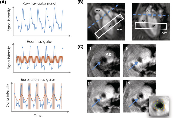
(A) Representative raw, cardiac, and respiratory navigator signal (top, middle, and bottom, respectively). In the middle panel, the red line indicates the cardiac signal extracted from the raw navigator. In the bottom panel, the red line indicates the extracted respiratory signal, while the red shaded areas indicate the detected respiratory motion. (B) Apparent long axis (left) and four‐chamber view (right) used for localizing the aorta root. Blue dashed line, aortic root plane. White rectangle, position of navigator slice. AA, ascending aorta; LV, left ventricle; nav, navigator; RV, right ventricle. (C) Representative images of the aortic root (AR; blue arrow) during the dynamic acquisition, including a representative tracing of the inner (green) and outer (orange) vessel wall counters for frame 19. The number in the top left corner of each panel indicates the corresponding dynamic frame