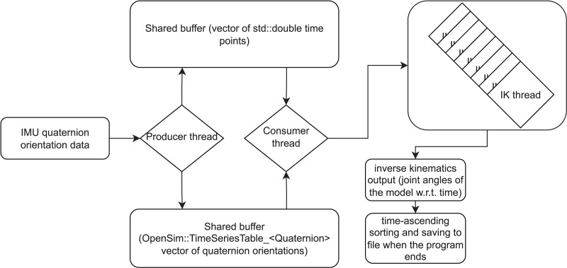
Figure 1. A diagram illustrating the working principle of the inverse kinematics (IK) workflow.
Orientation data of inertial measurement units (IMUs) is read as quaternions by the producer thread and saved to a buffer. Time values are saved to another buffer. The consumer thread reads data from both buffers and initiates new threads that calculate IK based on the data. IK threads output joint angle values for the model. Within an IK thread, the IK output can be sent to a visualizer window. The visualization is based on the Simbody (i.e., the physics engine used by OpenSim) API and not a part of our software library and hence not described here in more detail. When the program finishes, the IK output frames can be sorted in a time-ascending order and saved to file.

