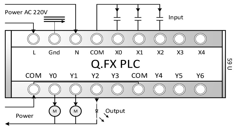
Figure 9.
The PLC corresponds to the X~X4 contacts, where X is the input contact, Y is the output contact, M is the external motor, and COM is the common parallel point. The L and N of the power supply represent the live and neutral wires, respectively. The Q and FX models are PLCs introduced by the MITSUBISHI Company. This PLC, designed for this system, allows the control logic program to be updated through the users such as the DT mapping model in DT-HMIS of this system, without being limited by the developer. Users/patients can also extend peripheral device control on their own.

