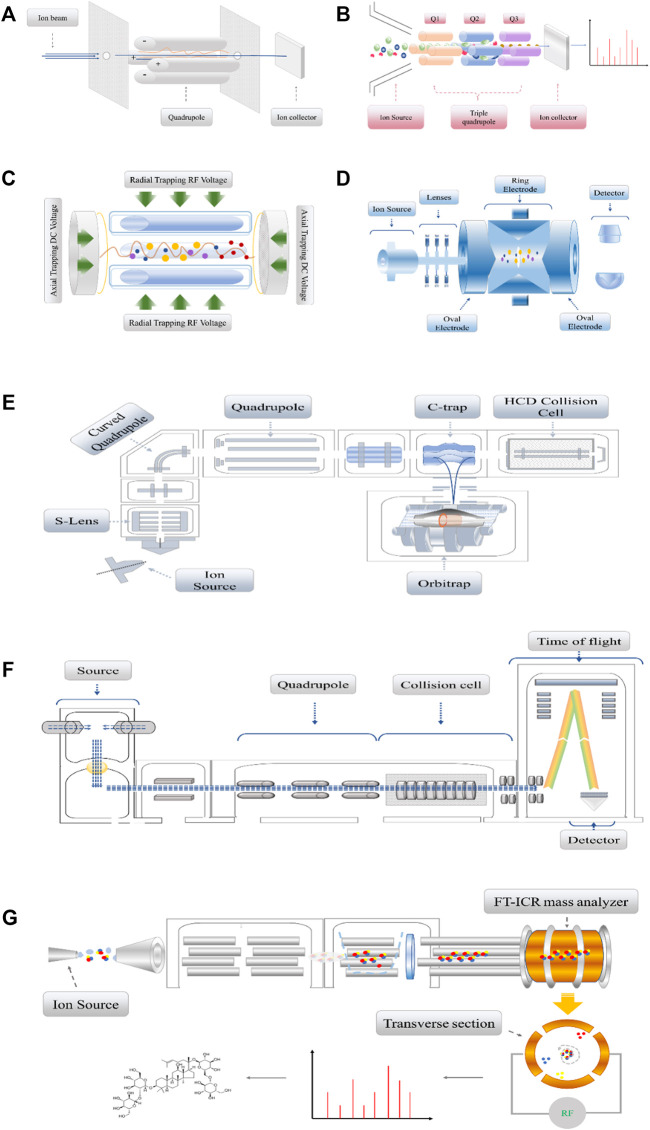
FIGURE 2.
(A). The single quadrupole detector consists of four parallel cylindrical or hyperbolic cylindrical electrodes which are equally spaced with the central axis to form two groups of positive and negative electrodes. The DC voltage and RF voltage in the x and y directions are applied to generate a dynamic electric field. (B). Triple quadrupole detector, which by breaking the sample in the ion source to obtain specific daughter ions, daughter ions by Q1, Q2, and Q3 after the selection of the receiver into electrical signals. (C). Linear ion trap, which are designed as three segments in their entirety, apply Radial Trapping RF Voltage and Axial Trapping DC Voltage between electrodes. (D). 3D ion trap diagram is composed of a ring electrode and two oval electrodes. Two oval electrodes have small holes as ion channels. Generally, RF AC voltage or DC voltage is applied on the ring electrode. (E). The Orbitrap detector, after ionization of the analytes in the Ion Source, will sequentially enter the Quadrupole, the C-trap, and the Orbitrap. If debris is also collected, the detected material will also be fragmented in a high-energy collision cell. It works like electrons rotate around the nucleus. (F). The schematic diagram of a substance passing through the Q-TOF mass spectrometer. According to the equation of kinetic energy with mass and velocity: E = mv2, ions with smaller mass-to-charge ratio will obtain higher velocity, shorter flight time, and then convert into mass spectra. (G). The FT-ICR mass spectrometer is a cavity with uniform superconducting magnetic field. Ions move in a circular orbit perpendicular to the magnetic field. When the cyclotron ion beam approaches a pair of traps, the image current signal will be detected on the traps, and the original data is transformed by Fourier transform to form a mass spectrum.

