Figure 1.

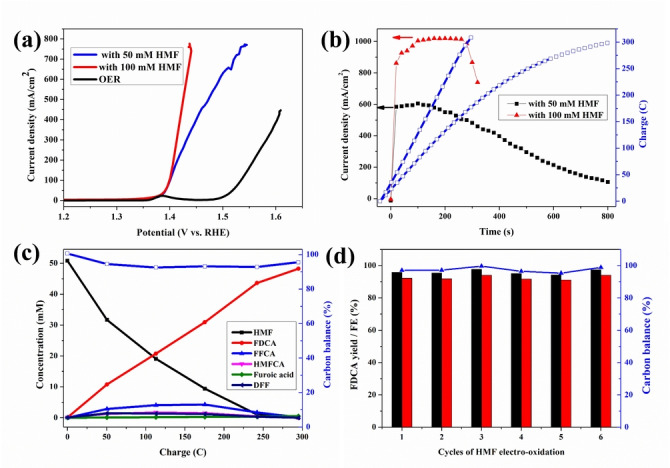
HMF electro‐oxidation over a NiFe‐1 electrode with different concentrations of HMF. a) LSVs (without iR compensation, results with 85 % iR compensation are shown in Figure S6), b) current densities, charges vs. time curves, c) conversion and concentration changes of HMF and its oxidation products during the electrochemical oxidation of 50 mM HMF, and d) recyclability test: the FDCA yields (black column), Faradaic efficiencies (FE, red column) and carbon balance (blue) during 50 mM HMF electrooxidation. Reaction condition: 1 M KOH, 50 mM or 100 mM HMF, applied potential 1.478 V (vs. RHE). Current density is calculated by normalizing the current to geometrical surface area of the electrode (10 mm ×10 mm, Supporting Information).
