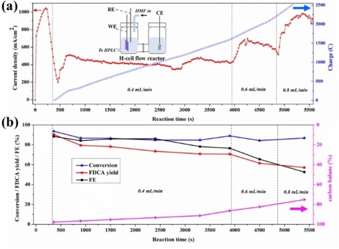
Figure 2.

HMF electro‐oxidation over NiFe‐1 electrode in a flow H‐cell configuration. a) Current densities, charge vs. time curves. Inset shows a cartoon of the H‐cell configuration used for single pass flow‐through reaction (WE, working electrode; RE, reference electrode; CE, counter electrode; HPLC, high‐performance liquid chromatography). b) HMF conversion, FDCA yield, FE and carbon balance during the flow cell HMF electro‐oxidation. All electrochemical tests are conducted in 1 M KOH with 100 mM HMF at the applied potential 1.478 V (vs. RHE) in an aqueous H‐cell configuration
