
Figure 9. Adjusting the scan range and offset to the rolling shutter of the camera.
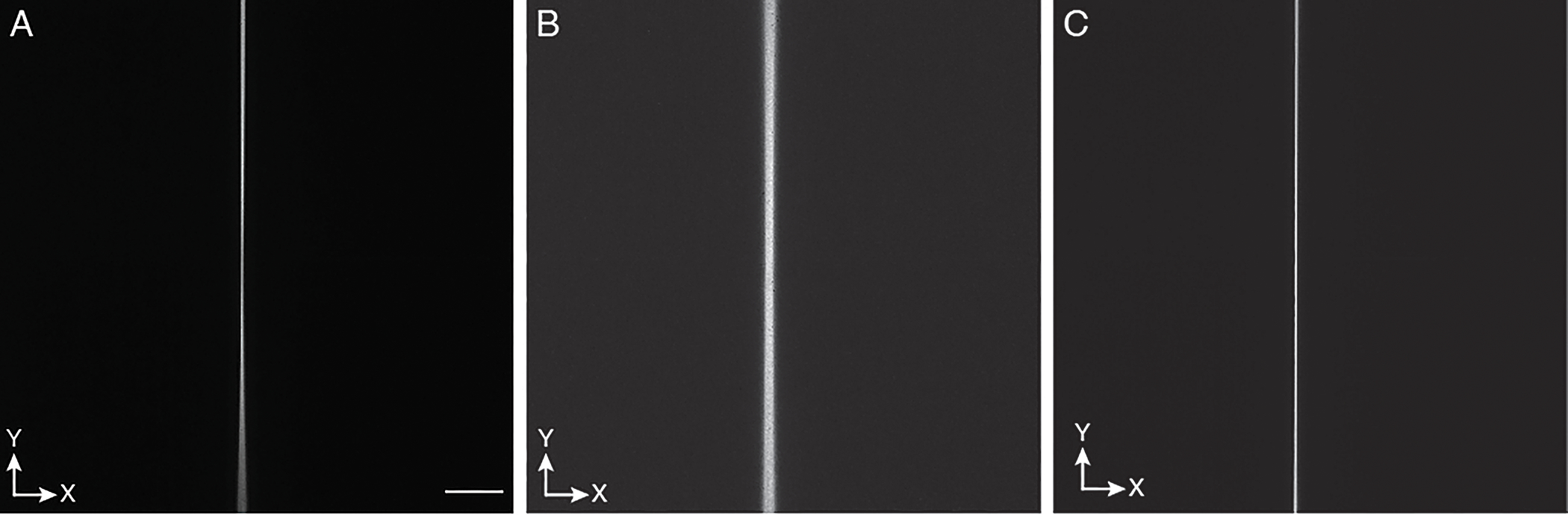
Scanning a 2D laser focus creates a line-shaped image: a, Example of a sub-optimal range for the laser scan, as one portion of the laser scan is out of sync with the camera rolling shutter. b, Example of a suboptimal offset for the scanning waveform for the laser focus: the laser focus is not in phase with the rolling shutter of the camera, leading to a blurry line. Note: blurriness of the line can also occur if the focal plane of the detection objective is off. c, Optimized range and offset for the scanning waveform. A thin line appears that does not change in width and brightness over the full field of view. The Y-direction is along the scan direction of the light-sheet. Scale bar: 100 microns.