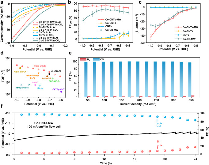
Fig. 2. Evaluation of CO2RR performances in the H-type cell and flow cell.
a LSV curves acquired in CO2-saturated (solid line) or Ar-saturated (dashed line) 0.5 M KHCO3 electrolyte, b CO Faradaic efficiencies and c CO partial current densities at various applied potentials on Co-CNTs-MW, Co-CNTs, CNTs, and Co-CB-MW in the H-type cell, respectively. The error bars represent the standard deviation of three measurements. d Calculated TOF of Co-CNTs-MW catalyst from c compared with state-of-the-art CO2-to-CO conversion electrocatalysts. A-Ni-NSG19, Co-N535, CoPc-CN/CNT36, COF-367-Co37, Perfluorinated CoPc38, Pd nanoparticle39, Co-TTCOF40, CATPyr/CNT41, and Ni-N-C42 were selected as references. More details were summarized in Table S2. e CO and H2 Faradaic efficiencies on Co-CNTs-MW catalyst in the range of current densities from 50 to 350 mA cm−2 in a flow cell configuration with 1.0 M KOH as electrolyte. f Long-term electrolysis under a current density of 100 mA cm−2 in the flow cell. After 20 h of testing at a current density of 100 mA cm−2, the catalyst still has a CO selectivity of up to 92.1%. The loadings of catalysts are 1.0 mg cm−2.

