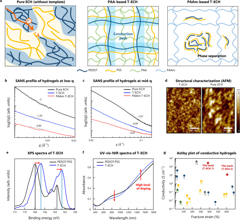
Fig. 3. Morphological and structural characterizations of T-ECH.
a Schematic illustration of microstructures of Pure ECH, T-ECH, and PAAm-based T-ECH (PAAm T-ECH). In Pure ECH, the electrically conductive pathway is disrupted by insulating PSS-rich domains. On the other hand, T-ECH has a continuous PEDOT-connected network without bulk PSS aggregates limiting the conductive pathway. PAAm-based T-ECH cannot have PEDOT fibrous network due to the phase separation of PEDOT:PSS and PAAm. b SANS measurements of Pure ECH, T-ECH (T-ECH 1), and PAAm-based T-ECH at low-q ranges (<0.02 Å−1). c SANS measurements of Pure ECH, T-ECH (T-ECH 1), and PAAm T-ECH at mid-q ranges (0.02 Å−1 < q < 0.14 Å−1). d AFM height images of T-ECH (left) and Pure ECH (right). Similar results were observed in two independent samples. e XPS spectra of the fully dried films of PEDOT:PSS (black) and T-ECH (blue). f UV-vis-NIR absorbance spectra of PEDOT:PSS (black) and T-ECH (blue). g Ashby plot of conductive hydrogels. PEDOT:PSS-based hydrogel (blue), polyaniline (PANI)-based hydrogel (yellow), polypyrrole (PPy)-based hydrogel (green), and metal-based hydrogel (gray) (Supplementary Fig. 1).

