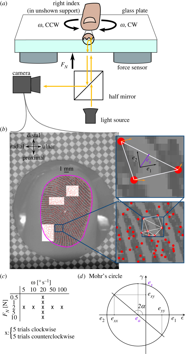
Figure 1.
Methods. (a) Participants rested the nail of their right index finger in a support, volar side pointing down. Below, a robot controlled the position of a smooth glass plate. The normal force applied was measured by two force and torque sensors located between the robot and the plate. The finger–plate contact was illuminated and filmed through the glass plate. (b) Video frame acquired by the apparatus. The border of the contact is shown in magenta. Features of the contact were tracked (red dots) and formed the vertices of a Delaunay mesh (white triangle). Areas of skin slipping and Green–Lagrange strains were derived from the skin displacement field (orange arrows). (c) Comparisons across normal forces were made for a fixed angular velocity (20° s−1), and comparisons across angular velocities for a fixed normal force (2 N). (d) Mohr’s circle is a graphical representation of the strain tensor in multiple coordinate systems. In Mohr-circle space, the abscissa and ordinate represent, respectively, the normal and shear strain. Each point on the circle represents the strain tensor in a given coordinate system obtained by rotation. A rotation of α in the physical world corresponds to a rotation of 2α in Mohr-circle space. The two intersections between the circle and the abscissa represent principal strains (absence of shear strain). The radius of the circle is the maximum shear strain, obtained in the coordinate system at 45° from the principal strains (90° in Mohr-circle space). The circle centre represents the average magnitude of the two principal strains or area invariant.

