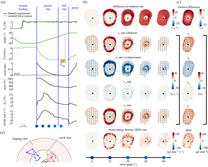
Figure 2.
Illustrative trial. Data come from both a trial with video recording and a corresponding trial with precise torque measurements, at 2 N, 20° s−1, counterclockwise, of Participant 2. (a) Time evolution of normal force, stimulus angle, torque, stick ratio, contact area, median of the maximum shear strain over the contact area and strain energy for an illustrative trial. Black traces come from one trial of the experiment with video recordings, while green traces come from a corresponding trial of the experiment measuring torque precisely with a force sensor directly under the finger. The horizontal dashed line on the stick ratio plot highlights the time and angle when full slip occurs. Blue dots correspond to the frames displayed in (b). (b) Various descriptions of the skin strain rates in rows, with columns showing snapshots at times represented by the blue dots in (a) throughout plate rotation. The centre of rotation is marked with a black dot. Rotation rate of the skin is expressed in the frame of reference of the rotating plate, with the increasing intensity of colour indicating a greater difference in rotation rates of skin and plate, implying that the skin is slipping. Two principal strain rates (e1 and e2) express the local deformation as purely dilation and compression (i.e. the local reference frame is chosen so that the shear component is zero), and associated eigenvectors are indicated by black lines. Area strain invariant (ea) describes the local change in skin area. The maximum shear rate (es) is determined by choosing the local coordinate frame such that the shear component of the local strains is maximized, at 45° from e1 and e2. Finally, the strain energy density is shown, which approximates the energy stored in the skin surface due to local deformations, assuming a Young’s modulus of 1 MPa and a Poisson ratio of 0.4. (c) The rightmost column shows the delta of the corresponding row variable between the last and first frames of the 80° rotation. (d) Schematic view of the finger with a region of the skin slipping and a region of the skin stuck to the plate. The area inside the large red oval represents the contact area, and the area inside the small white oval represents the skin stuck to the glass. The red triangle represents a triangular skin element with all its vertices inside the stuck part of the skin, and the blue triangle represents a triangular skin element with two of its vertices in the part of the skin slipping and one vertex in the part of the skin stuck to the plate. The black dot indicates the centre of rotation, and the black arrow indicates the rotation direction of the plate. The difference in the rotation rate between the red triangle and the plate is 0, while it is greater than ω between the blue triangle and the plate.

