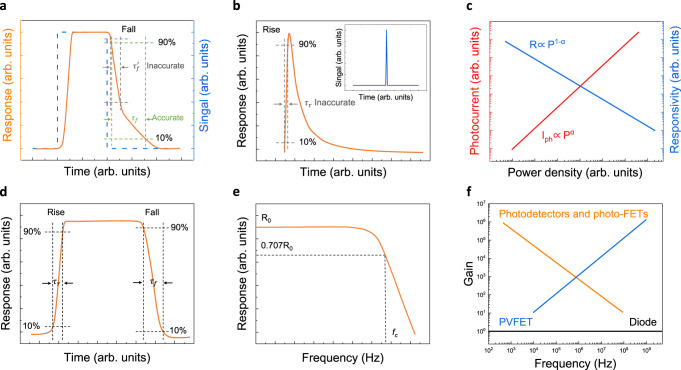
Fig. 6. Time parameters and gain determination of 2D photodetectors.
a Calculated fall time does not reach a stable value which is inaccurate, where is inaccurate calculated fall time, is accurate calculated fall time. (The bule line represents the square signal curve, the yellow line represents the typical response curve of 2D photodetectors.) b Response time measurement of photodetector may not reach a stable value under pulse signal, which will lead to an inaccurate result. The inset shows pulse signal. The is inaccurate calculated rise time. c Variation of photocurrent and responsivity of photoconductive photodetectors with the incident optical power density14. d Rise and fall response time of photodetector should be calculated from a complete periodic signal. e Typical −3 dB bandwidth response curve of photodetector, where represents stable responsivity value, represents the −3 dB cutoff frequency. f Gain-bandwidth product of various photodetectors, where photo-FET is photo-field-effect transistor, PVFET is photovoltage field-effect transistor14.

