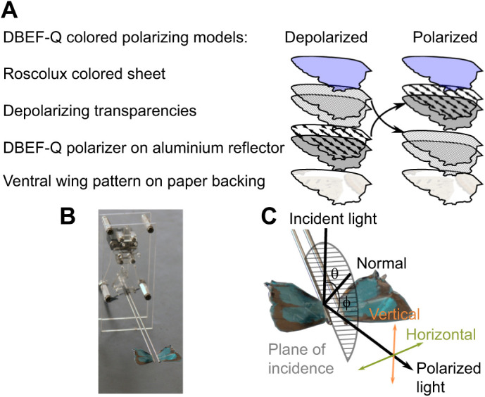
Fig. 2.

Mock wing construction and robot assembly. (A) Mock wing layers for polarized and depolarized DBEF-Q treatments (see Materials and Methods for further details). (B) Robotic wing beater assembly with blue (R374) DBEF-Q wing treatment affixed. (C) Diagram describing the definitions of polarization employed to fabricate and characterize model and specimen wings. ‘Horizontal’ represents polarization perpendicular to the plane of incident light (semicircle); ‘Vertical’ represents polarization parallel to the plane of incident light. Angles of incident light (θ) and detection angle (ϕ) are both relative to normal (vertical from the specimen).
