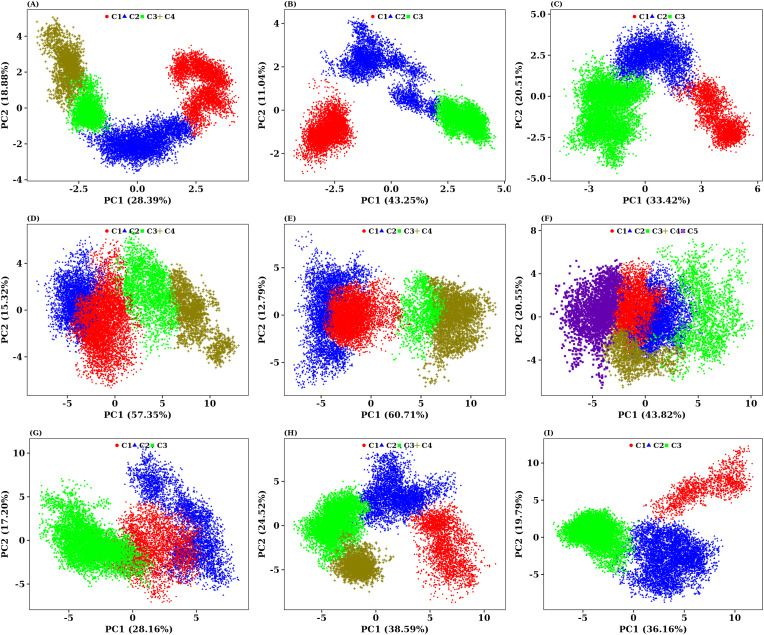
Fig. 10.
Principal component analysis revealing the dynamics of motion for all nine mapped ligand-bound complexes. Projection of motion in phase space along the PC1 and PC2 is drawn as scatter plot. (A) PCA plot of I7L-BAT complex. (B) PCA plot of I7L-BUR complex. (C) PCA plot of I7L-ELU complex. (D) (A) PCA plot of Top1B-BAT complex. (E) PCA plot of Top1B-BUR complex. (F) PCA plot of Top1B-ELU complex. (G) PCA plot of VETFS-BAT complex. (H) PCA plot of VETFS-BUR complex. (I) PCA plot of VETFS-ELU complex. The coloured dots in every PCA plot correspond to the sub clusters formed by each protein in complex with its respective ligand during 150 ns of simulation. The explained variance (%) of each principal component are presented in brackets.

