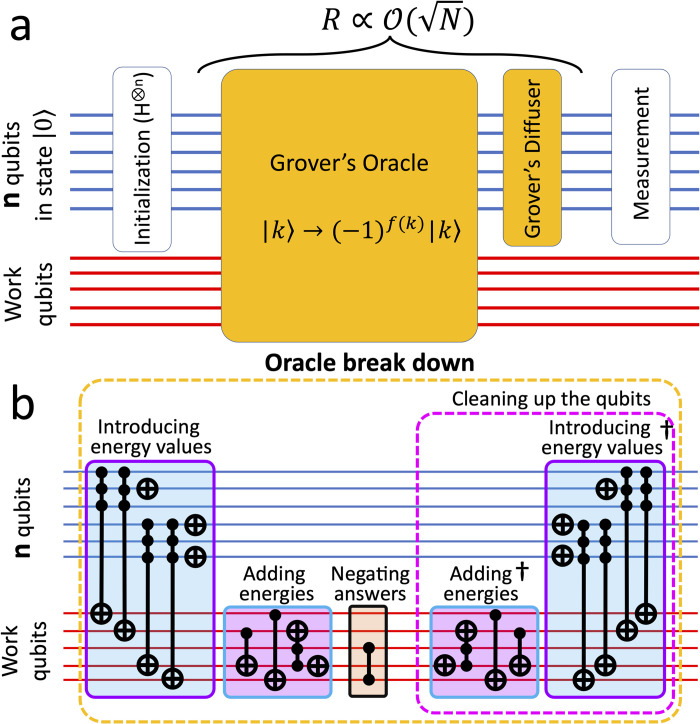
Fig 1. Schematic representation of our circuits.
A) Different steps of Grover’s algorithm; B) Different sub-steps implemented in our Oracle. The parallel lines represent qubits. The blue lines show the n qubits and the red lines show the work qubits. In the oracle, if |k〉 is an answer state, f(k) = 1, otherwise it is 0.

