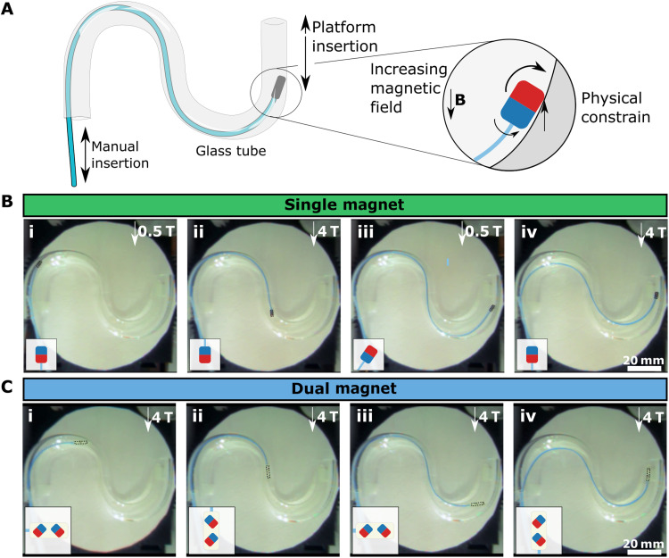
Fig. 6. In situ magnetization switch demonstration for orientation locking.
(A) Schematic illustration of the orientation locking experimental setup. An S-shaped glass tube is used to demonstrate the magnetization switch inside constrained tubular structures. The guidewire is manually inserted by hand, and the platform motion in the x direction is controlled remotely. The schematic showed the physical constraining procedure in the tube. (B) The magnetization switching with a single parallel magnet. The guidewire is inserted in the tube at a low field of 0.5 T, and the magnetic field is increased by moving the platform in the MRI scanner when the magnet is physically constrained (iii). The state of the magnetization direction is shown in the schematics. (C) The magnetization switching with a dual magnet configuration. The snapshots are captured at three different magnetic orientations during the guidewire insertion.

