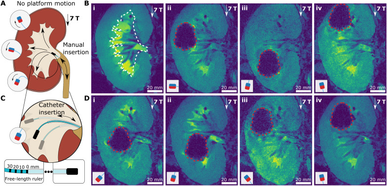
Fig. 8. UHF guidewire steering during MRI.
(A) Schematic illustration of a navigation experiment in a renal cavity of a porcine kidney ex vivo. The kidney was placed at the MRI imaging center, i.e., uniform 7-T magnetic field, and not moved during guidewire steering in the renal cavity. The guidewire was inserted through the urethra. The three target directions and corresponding magnetic tip configurations are shown. (B) MR images of guidewire insertion. The approximate boundaries of the renal cavity were shown with white dashed lines on the preoperational MRI image of the kidney (i). Then, the real-time MR image snapshots of the guidewires with perpendicular (ii), antiparallel (iii), and parallel (iv) magnets were shown in the renal cavity. (C) Supporting catheter-based steering of the guidewire. The three cases of different guidewire free lengths are depicted for antiparallel magnet configuration. The free-length ruler with the supporting catheter is shown at the bottom. (D) MR images of guidewire steering. The guidewire with the antiparallel magnet, as shown in (i) and (ii), with guidewire free lengths of 0 and 20 mm, respectively. The guidewire with the parallel magnet, as shown in (iii) and (iv), with guidewire free lengths of 0 and 20 mm, respectively. The boundaries of the tip magnet MR image artifacts are shown with red dashed lines. The magnetic configurations are shown in the small schematic in each frame. Scale bars, 20 mm.

