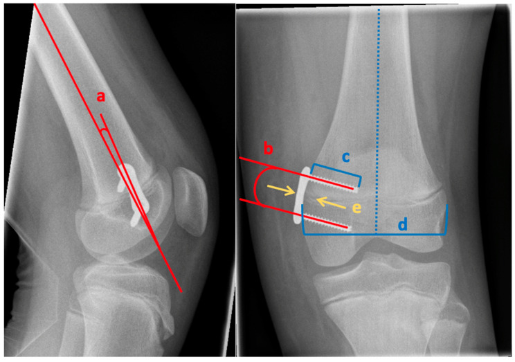
Figure 2.
Radiological assessment: a—angle between the implant and femur axis, b—angle between the two screws, c—length of the screw, d—width of the epiphysis (greatest width of the epiphysis perpendicular to the axis of the femur), e—relation of the center of the plate to the physis (left arrow pointing at the center of the plate and right arrow pointing at the center of the physis).

