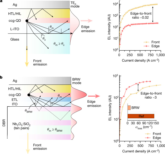
Fig. 2. Guided optical modes in the reference and BRW devices.
a,b Left, cross-sectional structure of the reference (a) and BRW (b) devices, along with the computed distribution of the TE modes (shown as red-shaded profiles). In the reference device, this mode is supported by TIR, whose critical angle (θc) is controlled by the refractive-index contrast at the L-ITO–glass interface (sinθc = nglass/nL-ITO). In the BRW device, the mode angle (θm = θBRW) is defined by the condition of constructive interference (Bragg condition) of reflections from different layers of the DBR. As a result, the optical-field profile exhibits an oscillatory pattern linked to the periodic structure of the DBR. Right, dependence of front-emitted and edge-emitted light intensities (yellow and red symbols, respectively) on current density for the reference (a) and BRW (b) devices. Owing to large propagation losses, the reference device radiates primarily from its front glass-cladded surface (the front-to-edge intensity ratio is about 50). By contrast, owing to reduced optical losses (inset in b, right) and strong amplification of guided light, the BRW emits more strongly from its edge (the edge-to-front intensity ratio is about 2 to 3). AU, arbitrary units.

