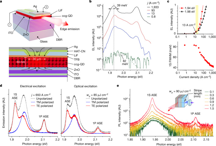
Fig. 3. Electrically driven ASE in the BRW device.
a, A BRW device is built on top of a DBR made of ten pairs of Nb2O5 and SiO2 layers. The device contains an ITO cathode, a ZnO ETL, a ccg-QD gain medium (three QD monolayers), a TFB HTL, a LiF interlayer with a current-focusing slit, a HAT-CN HIL and a strip-like Ag anode. b, Edge-emitted EL spectra of the BRW device as a function of current density tuned from 0.8 to 1,933 A cm−2. The device was excited using pulsed bias with τp = 1 μs and pulse-to-pulse separation T = 1 ms. The EL spectra show a transition from broad spontaneous emission observed at low j to sharp 1S and 1P ASE bands at high j. c, Top, the j-dependent EL intensities at the peaks of the 1S spontaneous (black) and ASE (red) bands indicate the ASE threshold jth,ASE ≈ 13 A cm−2. Bottom, the dependence of 1S emission linewidth on j indicates progressive line narrowing from 82 to 39 meV. d, Polarization characteristics of edge-emitted light of the BRW device in the case of electrical (left, j = 650 A cm−2) and optical (right, 110-fs, 3.6-eV pulses, wp = 85 μJ cm−2) excitation. Owing to strong damping of TM modes, the 1S and 1P ASE bands are not present in TM-polarized emission (blue) and exhibit nearly perfect TE polarization (red). The spontaneous 1S band is not polarized (black) and, as a result, is present in both TE-polarized and TM-polarized emission. e, The VSL measurements of the optically excited BRW device (inset) indicate the development of the 1S and 1P ASE features with increasing stripe length. These measurements used 110-fs, 3.6-eV pump pulses with wp = 90 μJ cm−2. The sharp ASE bands are similar to those observed in the EL spectra (panel b). AU, arbitrary units.

