
Figure 2.
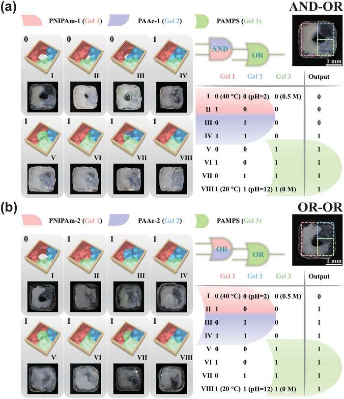
Schematic illustrations and images of the microrobots in the different states with connected logic gates and the truth tables. a) An AND gate connected with an OR gate. b) An OR gate connected with another OR gate.
Official websites use .gov
A
.gov website belongs to an official
government organization in the United States.
Secure .gov websites use HTTPS
A lock (
) or https:// means you've safely
connected to the .gov website. Share sensitive
information only on official, secure websites.
Schematic illustrations and images of the microrobots in the different states with connected logic gates and the truth tables. a) An AND gate connected with an OR gate. b) An OR gate connected with another OR gate.