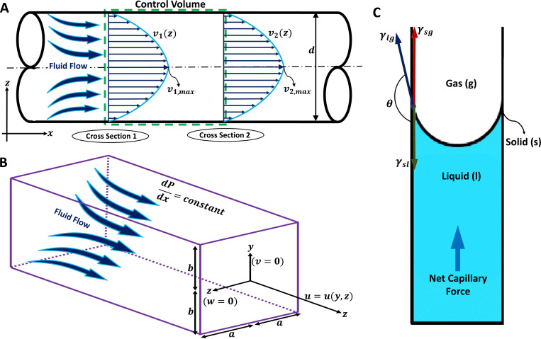
FIG. 5.
Fluid flow transportation modeling in hollow microchannels and microchannels for drug delivery and sampling applications. (a) A two-dimensional microchannel demonstration with a circular cross section and diameter d is illustrated. The fully developed fluid flow equations inside the microchannel can be determined by applying the energy equation to the control volume. Considering fully developed flow, velocity profile, v, will be only a function of z in each cross section. The maximum velocity profile in each cross section should be considered for calculating the average fluid velocity for each cross section. (b) A three-dimensional microchannel demonstration with a rectangular cross section in which corresponds to the width and considered as the height. The fully developed fluid flow equations inside the microchannel can be determined using the Poiseuille flow equation. Considering a constant pressure distribution in x direction, the fluid velocity vector only has its x component which is a function of y and z in each cross section. (c) Schematic diagram of the capillary action for fluid extraction from the skin. Three surface tensions act on the solid–liquid–gas boundaries, which are demonstrated as solid–liquid surface tension, , liquid–gas surface tension, , and solid–gas surface tension, in which represents the angle between and . Subfigure (c) reproduced with permission from Mukerjee et al.,1 Sens. Actuator A 114(2–3), 267–275 (2004). Copyright 2004 Elsevier B.V.

