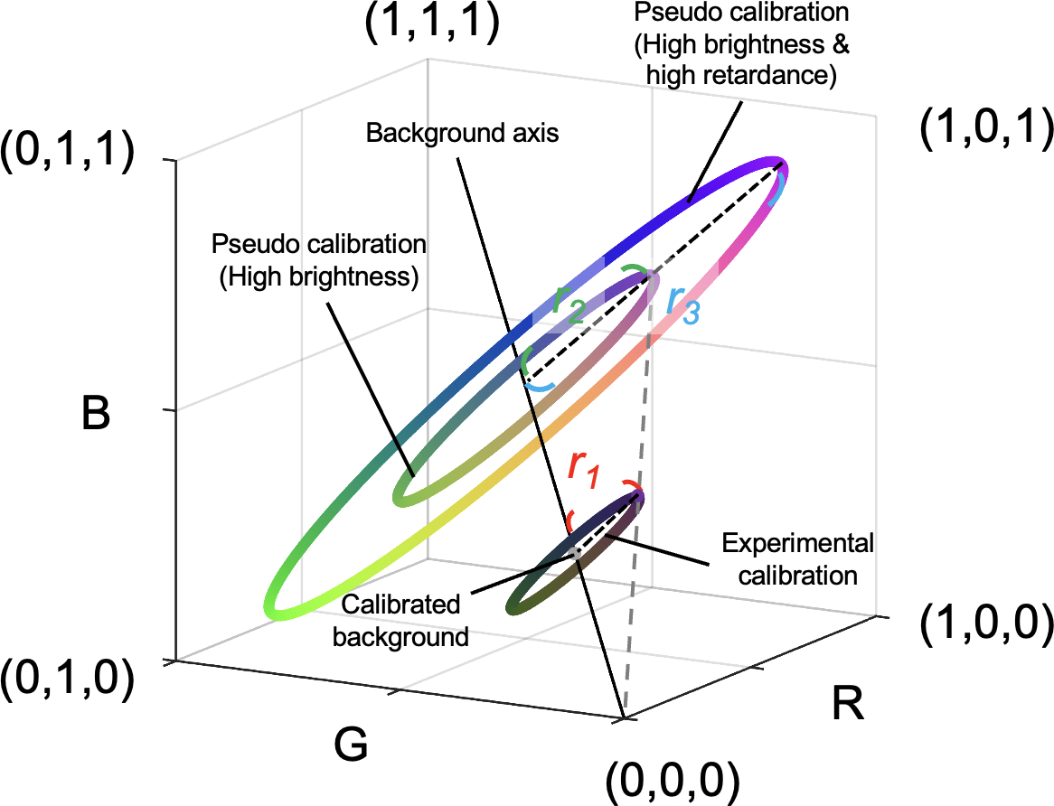
Figure 2.

Generation of pseudo calibrations from the experimental calibration. An experimental calibration created a ring with a calibrated background (i.e., central point) and a radius r1 in the color space. We defined the RGB distance between color on experimental calibration and calibrated background (i.e., radius) as a unit of “energy”, which was related to retardance. Pseudo calibrated rings were generated based on changes in brightness and energy. On one hand, an increase in brightness results in an increase in RGB values in proportion due to exposure time or tissue absorptance. For example, a pseudo calibration ring with a radius r2 represents a higher exposure time or lower tissue absorption than the experimental calibrated result. Although their radiuses are different, both have the same energy. On the other hand, an increase in energy results in an increase in the radius of the calibrated ring in proportion. For example, a sample generating a calibrated ring with a radius r3 has higher energy than a sample generating a calibrated ring with a radius r2. A combination of pseudo and experimental calibrations was used to build interpolating functions for orientation and energy inquiry.
