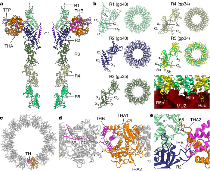
Fig. 4. The tail barrel and fibre docking hubs.
a, Two opposing chains of ring proteins of the tail barrel, depicted as ribbon diagram, from top to bottom: R1 (gp43) (light cyan), R2 (gp40) (navy), R3 (gp35) (mid green), R4 (gp34) and R5 (gp34) (light green), THA (gp38) (orange), THB (gp39) (pink) and gp22 (dark grey). b, Individual subunits of each ring protein alongside their dodecameric ring assemblies viewed along the central axis. c, The collar formed by 12 tail hub assemblies, viewed along the central axis from the capsid end, depicted in ribbon diagram with chains of one tail hub coloured orange for THA1 and THA2 and pink for THB. TH, tail hub. d, The collar as in c, rotated 90° and enlarged, showing interlocking tail hubs. e, Enlarged view of disulfide bonds (yellow, ball and stick) between tail hub proteins and R1 and R2 proteins. Asterisks designate disulfide bonds.

