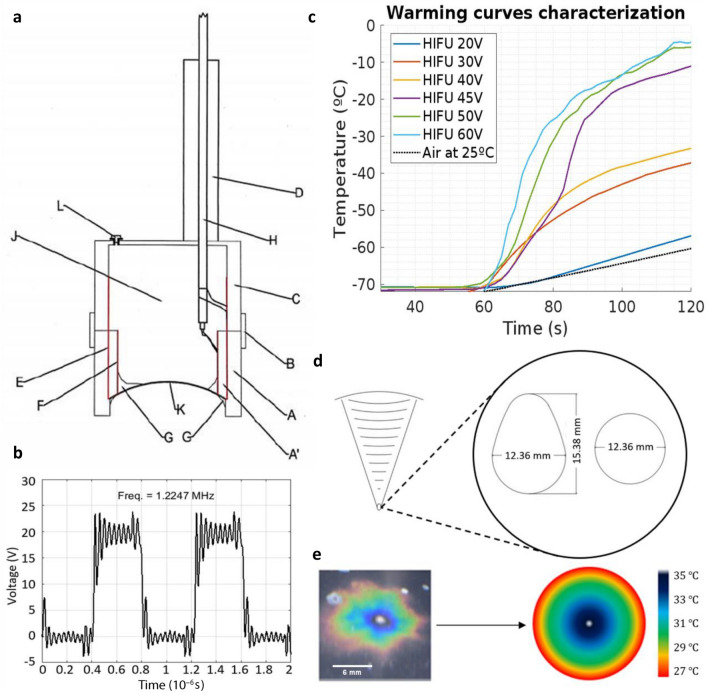
Figure 2.
Characterization of the High Intensity Focused Ultrasound equipment. (a) Section of the HIFU transducer. A–D: PVC chassis, to provide structure, sealing and air chamber behind the cap; E: conductive film for the outer surface of the cap; F: conductive film for the inner surface of the cap; G: epoxy sealant (external and internal); H: power coaxial cable; J: air chamber; K: PTZ-8 ceramic ball cap; L: drain plug for the air chamber in case of infiltration. (b) Square wave generator output, without power supply from the external source. The signal frequency is 1.22 MHz, with an amplitude of 18 V peak-peak. (c) Temperature curves obtained by heating with HIFU at different voltages and currents of the external power supply. The shots were normalized for 60 s of exposure. The obtained warming rates depended on the power supply of the external source. As the nominal power of the piezo is 25W, operating below it (case of the curve for 20 V and 0.68 A) results in reduced performance. (d) Detail of the focal region of ultrasonic heating. Heat transfer is greatest in an ovoid region of dimensions 12 × 15 mm. These values were obtained from the experiments by thermography with thermosensitive film, whose example is shown in (e). (e) Thermographic profile of heating with HIFU in water at room temperature. The heating produces, in the section, concentric circles with respect to the focus. Between the hottest and the coldest point, a temperature difference of less than is always recorded.

