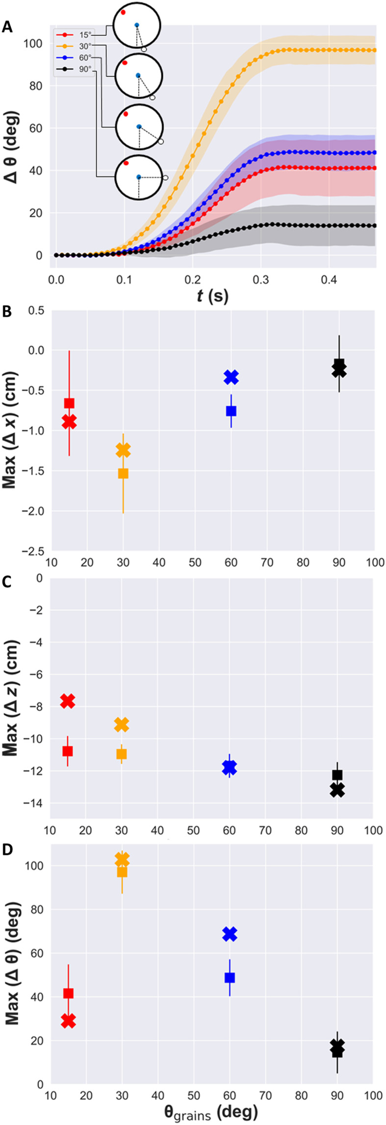
Fig. 2. Intruders with a row of grains attached to the right face (Scarface Janus cylinders).
(A) Experimental results for the rotation angle versus time for Scarface when a row of grains is attached at different angular positions relative to the vertical, θgrains, as sketched in the inset (the dotted lines are averages more than 10 repetitions of each experiment). (B to D) Maximum horizontal displacement, vertical displacement, and rotation angle as a function of θgrains, respectively. In (B) to (D), squares correspond to experimental results, and crosses correspond to a theoretical model explained in the text. The colored bands in (A) and the error bars in (B) to (D) correspond to the SD after 10 repetitions of each experiment.

