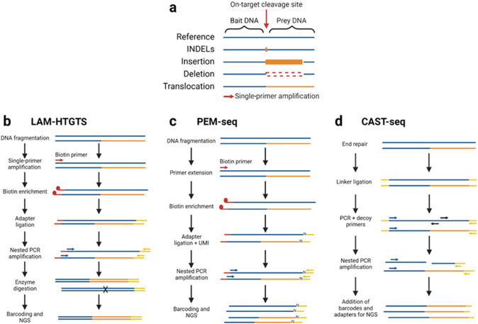
Fig. 2.
Diagrammatic overview of the bait/prey DNA system and SV capture techniques. a The bait DNA is the known sequence of DNA before the on-target cleavage site, which is followed by the prey DNA, the known sequence of DNA after the on-target cleavage site. Single-primer amplification from the bait DNA into the prey DNA can capture SV boundaries. b–d Schematic representations of the three SV capture techniques, LAM-HTGTS, PEM-seq, and CAST-seq which are described in detail in Sect. 3.4. Each diagram represents the workflow of the three techniques with one unedited allele (blue) and one allele with a translocation (blue/orange). The on-target cleavage site is located in the center of each amplicon (not depicted). Biotinylated primer sequences are shown in red, while linker and adapter sequences are in yellow. Primers are indicated by colored arrows and may be specific to the bait or prey DNA (blue, or red if biotinylated) or the linker/adapter sequence (yellow) b Enzymatic digestion of amplicons containing the unedited prey DNA sequence is indicated by the cross, ‘X’. c Unique molecular identifiers (UMI) which are added during adapter ligation are indicated by the ‘N’ on each amplicon. d ‘Decoy primers’ (black) are specific to the amplicons which contain the unedited prey sequence

