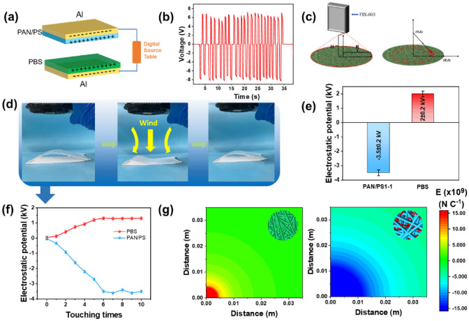
Fig. 4.
a Schematic diagram of the PAN/PS-PBS (TENG) structure, b measurement of open circuit voltage of self-powered structure with digital source meter, c schematic diagram of surface potential measurement, d contact-separation of self-powered structure when air flow passes through, e surface potential of the PAN/PS composite mat and PBS fiber membrane after contact separation cycles, f change of surface potential of the PAN/PS composite mat and PBS membrane during cyclic contact-separation, g electric field strength of PBS and PAN/PS single fiber after contact-separation

