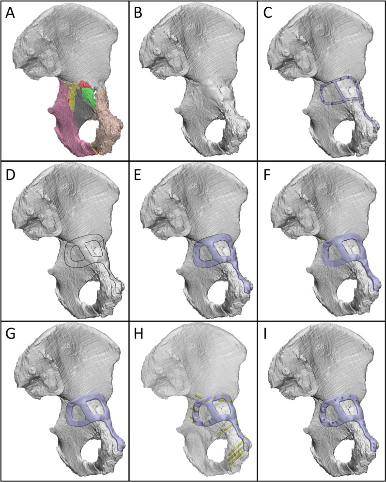
Fig. 1.
Design workflow for creating customised fracture plates. A Left hemipelvis with reduced fracture. Each piece of bone is indicated by a different colour. B Hemipelvis (grey) with fracture lines closed. C Intended path of plate (silver) and screw positions (red). D Curves indicating plate outline. E Plate lower surface, offset above bone by 0.2 mm. F Extruded plate geometry. G Plate geometry with filleted edges. H Plate and trajectories of 3.5 mm bicortical screws (yellow cylinders). The hemipelvis is displayed as transparent for visualisation. I Plate with holes cut through by screw cylinders

