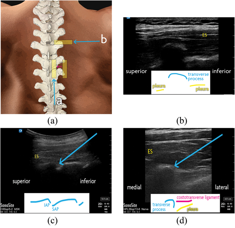
Figure 4.

Thoracic facet joint interventions. (a) Surface anatomy of the thoracic spine. The ultrasound transducer positions are demonstrated with a yellow rectangle. Scanning from lateral to medial (a; pink arrow), the ribs may be seen transitioning to the thoracic facet joints, then the laminae and facet joints, and finally the spinous processes in midline. The in-plane inferior-to-superior needle trajectory for (a) thoracic intra-articular injection is shown with a blue arrow. The transverse transducer position and in-plane lateral-to-medial needle trajectory is also shown for (b) thoracic medial branch block, at the superolateral aspect of the desired level’s transverse process. (b) Thoracic transverse process, as seen with an ultrasound transducer in saggital orientation. (c) Thoracic facet joints, as seen with an ultrasound transducer in saggital orientation. For intra-articular injection, the needle (blue arrow) is advanced in-plane to the target from an inferior-to-superior trajectory. (d) Thoracic medial branch block. With an ultrasound transducer in transverse orientation, the needle (blue arrow) is advanced in-plane to the target from a lateral-to-medial trajectory. For T5 to T8 medial branch block, the transducer is swept just superior to this view (not shown) and the needle is advance in-plane from a lateral-to-medial trajectory to intertransverse space, at a depth no deeper than the surface of the adjacent transverse processes. ES = erector spinae muscles; IAP = inferior articular process; SAP = superior articular process.
