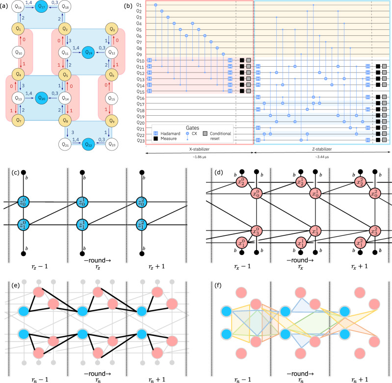
Fig. 1. Heavy-hexagon code.
a Z (blue) and X (red) gauge operators (eqs. (1) and (2)) mapped onto the 23 qubits required with the distance-3 heavy-hexagon code. Code qubits (Q1 − Q9) are shown in yellow, syndrome qubits (Q17, Q19, Q20, Q22) used for Z stabilizers in blue, and flag qubits and syndromes used in X stabilizers in white. The order and direction that CX gates are applied within each sub-section (0 to 4) are denoted by the numbered arrows. b Circuit diagram of one syndrome measurement round, including both X and Z stabilizers. The circuit diagram illustrates permitted parallelization of gate operations: those within the bounds set by scheduling barriers (vertical dashed gray lines). As each two-qubit gate duration differs, the final gate scheduling is determined with a standard as-late-as-possible circuit transpilation pass; after which dynamical decoupling is added to data qubits where time permits. Measurement and reset operations are isolated from other gate operations by barriers to allow for uniform dynamical decoupling to be added to idling data qubits. Decoding graphs for three rounds of (c) Z and (d) X stabilizer measurements with circuit-level noise allow correction of X and Z errors, respectively. The blue and red nodes in the graphs correspond to difference syndromes, while the black nodes are the boundary. Edges encode various ways errors can occur in the circuit as described in the text. Nodes are labeled by the type of stabilizer measurement (Z or X), along with a subscripts indexing the stabilizer, and superscripts denoting the round. e Black edges, arising from Pauli Y errors on code qubits (and so are just size-2), connect the two graphs in c and d, but are not used in the matching decoder. f The size-4 hyperedges, which are not used by matching, but are used in the maximum likelihood decoder. Colors are just for clarity. Translating each in time by one round also gives a valid hyperedge (with some variation at the time boundaries). Also not shown are any of the size-3 hyperedges.

