
Fig. 2.
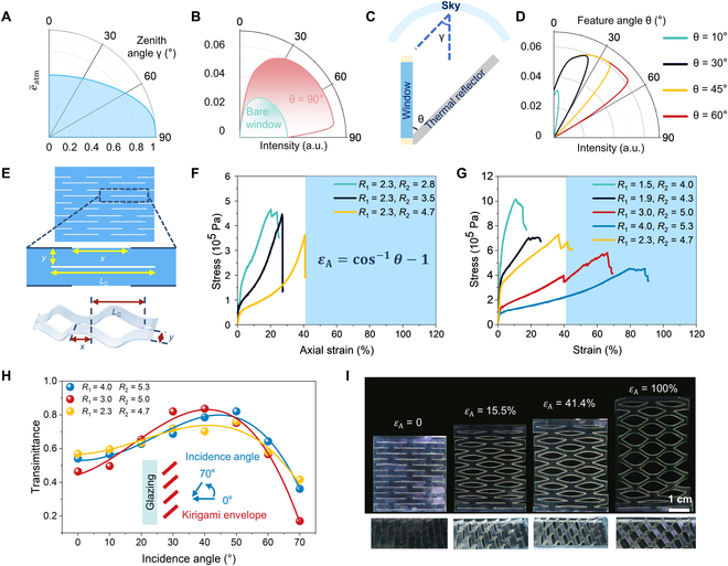
The design of optimal kirigami structure with radiation angle modulation. (A) The simulated emissivity of atmospheric radiation received by a vertically placed window at different zenith angles. (B) The simulated angular radiative intensity distribution of a bare window (green curve) and the window with a horizontal thermal reflector (pink curve). (C) Vertically placed window and thermal reflector as simplified geometry diagram of the kirigami structure. (D) The thermal radiation intensity of the window with thermal reflector placed at different feature angles. (E) Key structural parameters of the kirigami structure. (F and G) Stress–strain curves of kirigami structures with different R1 and R2. (H) Tlum of different kirigami structures along different incidence angles with the schematic illustration of the measurement in the inset. (I) The pictures of the stretched kirigami structure under different εA.